Full Equations (FEQ) Model for the Solution of the Full, Dynamic Equations of Motion for One-Dimensional Unsteady Flow in Open Channels and Through Control Structures
The input to FEQ is broken into blocks. A block consists of one or more tables. A table is a series of lines grouped on some basis. Each block begins with one or more lines of alphanumeric information (called a heading or headings) that delimits the block from the previous input. This is followed with the table or tables of information relevant to that block. The order of the blocks must be maintained. Furthermore, a value input in one block may require that a block of related information appear later in the input sequence to FEQ. For example, the Wind Information Block (section 13.8) is only given if WIND=YES in the Run Control Block (section 13.1).
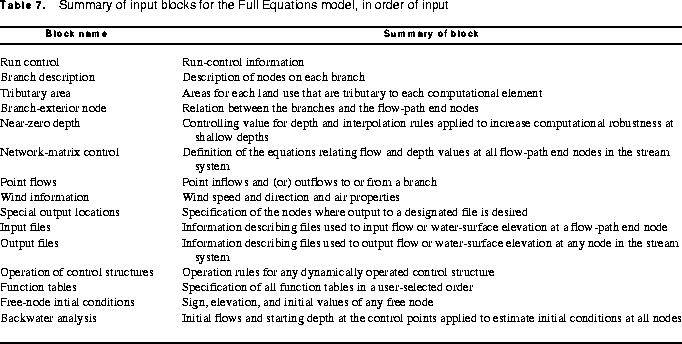
The input blocks used in simulation of unsteady flow in FEQ are
listed in table 7. The order of presentation in table 7 and in
this section is the order in which the blocks must be given in
the input sequence with the exception of the Function Tables
Block (section 13.13). This block may be present in two
locations: the location given here or before the Branch
Description Block (section 13.2).
Comments can be added at any line in the input if the first column of the line contains either an asterisk (*) or a semicolon (;). If the first character is an asterisk, then the comment is read and written to the output file. If the first character is a semicolon, then the comment is read but not written to the output file. All heading and label lines as described in the input must appear in the proper order. However, the addition of comments allows the input to be labeled or described in as much detail as desired.
Format Descriptions. In the line descriptions that follow the input format codes used are the same as for the Fortran language. An "X" format code indicates skipping the number of spaces given by the number preceding the X. The "A" format code indicates that a character string with no more characters given than the number following the A is to be entered. A character string is any sequence of characters that can be printed. Numbers, letters, and most special characters can be used in character strings. Character strings should be left justified in the specified field on the input line unless other instructions are given. The "I " format indicates an integer number with the maximum number of digits given by the number following the I. No decimal point should appear in an integer number. The number can appear anywhere within the assigned field. The "F " format code indicates a floating point number that can include a decimal point; in FEQ input, this number should always include a decimal point unless the number completely fills the field. The field width is given by the number following the F. A number preceding the A, I, or F format codes denotes repetition of that field width and type the given number of times. Thus, 8F5.0 indicates 8 fields each 5 columns wide and containing a number with a decimal point.
Reference to Files. Many files are used in FEQ simulation. Twenty or more files can be referenced in a complex stream system. The file described by this input description is often called the input file. However, other files will supply information to FEQ and could be considered input files. Function tables can be placed in one or more files and these files can then be referenced in the input to FEQ for access to part of the input. These files are called function table files or auxiliary files. Function tables also can be placed directly in the main input file for FEQ simulation.
Files are available that transfer flow or water-surface-elevation data between segments of the stream system simulated in FEQ. A stream system may be so large that a single model may be unwieldy. Therefore, under appropriate conditions, the user can develop two models; for example, one upstream and the other downstream from a control point. The upstream boundary for the downstream model must be supplied by the results at the downstream boundary on the upstream model. This is done in a special file developed from the results of the upstream model, sometimes referred to as a connection file or also a point-time series file. The file name is given in the Input Files Block (section 13.10) in the input to FEQ. Sometimes these files contain water-surface elevation data. When these files contain flow data, they could be referred to as inflow files.
One or more files are developed in FEQ in the process of simulating a stream. The primary output file, commonly just called the output file, includes information on how the input has been processed. The input, as read and interpreted in FEQ, is placed in the output file together with error and warning messages. A complete record of the results also can be placed in the output file, as specified by the user. This complete record includes results at every node in the system for every time step. This file can be many megabytes in length. Usually, the output file is restricted to include summary information about the results, and detailed information is included in what is called a special-output file. An output connection file also can be developed; details are given in the Output Files Block (section 13.11).
Files are available to record the hydraulic conditions in the model calculations so that computations can begin at the exact point of where the previous simulation stopped. This feature is useful for forecasting operations. A diffuse time-series file also may be used. A point-time series file represents the flow at a point in the stream, such as a downstream or upstream boundary. A diffuse time-series file represents the flows that originate from an area, where no particular point can be identified as the location where the flow enters the stream system. Descriptions of point-time series files and diffuse-time series files are given in appendix 2.