Full Equations Utilities (FEQUTL) Model for the Approximation of Hydraulic Characteristics of Open Channels and Control Structures During Unsteady Flow
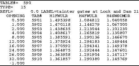
One type of 3-D table, type 15, is prepared with FEQUTL. An example of such a table is as follows.

This table is used to describe the flows through underflow gates, such as sluice gates and tainter gates, as a function of the gate opening, the piezometric head at the approach section to the gate, and the piezometric head at the departure section from the gate. The configuration, operation, and simulation of underflow gates are described in detail in section 4.8, and the computations for underflow gates are done in the UFGATE command (section 5.20). A table of type 15 lists for each gate opening, described by the vertical extent of the assumed rectangular opening, the table number of the 2-D table of type 13 that describes the flow for that gate setting. Three additional values are tabulated in the table for each gate opening. These values describe boundaries among flow conditions. H1FWULR is the ratio of the upstream piezometric head at section 1 (approach section) at the upper limit of free-weir flow to the gate opening; H4FWULR is the ratio of the piezometric head at section 4 (departure section) at the upper limit of free-weir flow to the gate opening; and H4SWSOMDR is the ratio of the piezometric head at section 4 at the boundary between submerged-weir flow and submerged-orifice flow for a head at section 1 midway between the head equal to the gate opening and the head equal to the upper limit of free-weir flow to the gate opening. Each of these variables is described in detail in section 4.8.
Interpolation within a table of type 15 is linear for all values except the table number. A look-up request in a table of type 15 returns five values: the pair of table numbers where the gate-opening heights bracket the current height of the gate opening and the three values used for defining boundaries between flow conditions. This only applies to one of the three arguments for the 3-D table. The other two arguments--the piezometric head at the approach section and the piezometric head at the departure section--are applied for table look up in the pair of 2-D tables determined in the table of type 15. The final interpolation, on gate opening, between the pair of 2-D tables is specific to the hydraulic characteristics of flow beneath underflow gates. This interpolation is described in section 4.8.