Enhancements and Modifications to the Full Equations Utilities (FEQUTL)
Model, March 1995 to August 1999.
Note: This document is separate from the U.S. Geological Survey report by Franz and Melching (1997). This description of enhancements and modifications to the Full Equations Utilities Model has not been approved by the Director of the U.S. Geological Survey.
New subsection for section 4. Approximation of Hydraulic Characteristics of Control Structures, Franz and Melching (1997b), p. 70
Section 4.7a Flow in Orifices
Orifices are sometimes used to slowly
release water from a detention reservoir to lower the water after a flood
event to prepare for the next flood event. The orifice is sized so that
the flow will not exceed a limit value for the design condition and to
also permit some minimum dry-weather flow to pass through the structure.
Orifice plates are also sometimes used as a retrofit on culverts whose
capacity proves to be too large for some change in conditions.
We define four flow conditions for
an orifice: free orifice flow (FO) in which the opening is filled with
water and the tailwater level is below the orifice invert; submerged orifice
flow (SO) in which the opening is filled with water but the tailwater level
is above the orifice invert; free weir flow (FW) in which the orifice opening
is only partially filled with water and the tailwater level is below the
invert; and submerged weir flow (SW) in which the orifice opening is only
partially filled with water but the tailwater is at or above the invert
of the orifice.
We do not assume any particular shape
to the orifice and the equations developed below apply to a wide range
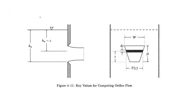
of shapes. Figure 4-11 shows a sketch of an orifice with some of the defining
dimensions. The greatest horizontal width of the orifice, called its horizontal
diameter, is denoted by  and its
greatest vertical height, called its vertical diameter, is denoted by
  .
The piezometric head upstream of the orifice is
  and the piezometric head downstream will be denoted by
  .
Following Rouse(1946) and Bos(1989) we estimate the incremental flow,
  ,
through the incremental strip of height
  and width,
  shown in
Figure 4-11 as

where  an incremental discharge coefficient that will vary with
  ,
and
,
and  as well as the
shape of the orifice and the nature of the edges of the opening; and
  acceleration due to gravity; and
  distance
of the strip from the orifice invert. We integrate this incremental flow
value from
  to
to  ,
assuming that the discharge coefficient will allow this to be done with
sufficient accuracy. We then get

where  the free orifice flow. We do not know the value of
  with any precision and the function would prove difficult to measure in
any case, so we make a further approximation, justified in part by the
first mean-value theorem for definite integrals, and use an average discharge
coefficient,
  , outside
the integral. With this change and with the transfer of the constant
  outside the integral, we get

as the defining equation for free-orifice flow. Note that the integrand in Eq. 4-31 is a function of the shape of the orifice and the current upstream head value. This equation applies to all shapes of orificesassuming a suitable value of discharge coefficient can be found for the shapes.
If the upstream head falls below the
top of the orifice opening, we get the defining equation for flow over
a sharp-crested weir. In this case, the upper limit of the integral becomes
the upstream head and not the vertical diameter. If we assume that we can
find a suitable discharge coefficient we can generalize Eq. 4-31 to include
free-weir flow also by changing the upper limit to include the two options.
That is, the upper limit will be the smaller of either the upstream head,  ,
or the vertical diameter of the opening,
  .
We then get

as the defining equation for both free orifice and free weir flow.


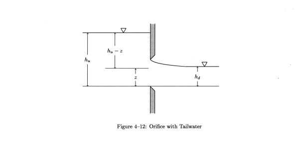
Figure 4-12 shows a sketch of our prototypical
orifice with a tailwater level added. There is no data in the literature
on orifice flow with the orifice partially under tailwater. However, such
a condition can exist, if only for a short time, during an unsteady flow
simulation and we must be able to describe it. The approach used here is
simple: we assume that the flow in the orifice below the tailwater level
is affected by the tailwater but that the flow in the orifice above the
tailwater level is not affected by the tailwater. Thus the submerged flow
is represented in two parts: one part is computed as if it were free and
the other as if it were completely submerged.
The free part is defined by changing
the lower limit on the integral in Eq. 4-32 to reflect that the flow may
be affected by tailwater. When the tailwater reaches the top of the orifice
the free-flow integral must vanish. Also the flow should be free of tailwater
if the head downstream is below the invert of the orifice. Thus the lower
limit becomes  to describe
all cases of interest. We then get the free part of the submerged flow,
  ,
for both orifice and weir flow as

Eq. 4-33 also defines free flow if  .
.
The net head on the submerged part
of the flow in the orifice is just the difference between the upstream
head and the downstream head, that is,  .
This head difference is a constant. If the orifice is not submerged at
all, we want the integral to be zero, and this gives an upper limit of
zero. If the orifice is partially submerged the upper limit should be
  .
Finally if the orifice is totally submerged, the upper limit should be
  .
This then gives

as the defining equation for the submerged
part of submerged flow for both weir and orifice flow if such flow exists.
If  then
then  .
Note that the integral gives the area of the orifice that is below the
tailwater level.
With this careful definition of integration
limits, the flow is given by  for all four flow conditions. Thus Eq. 4-33 and 4-34 are the defining equations
for all flow conditions for orifices in FEQUTL. Note that these equations
apply to all shapes for which it is meaningful to define a discharge coefficient.
We could specialize to particular
shapes and develop equations for each shape. However, we choose not to
do so. Instead, we will evaluate the defining integrals numerically so
that all shapes of interest are computed in the same way and with the same
equations. This will be done even in those cases were the integrals for
a particular shape can be computed in closed analytical form. The computational
cost of doing so is nil in comparison to the possibility of error in transcribing
the sometimes complex expressions for the integrals. By using the basic
definitions for the flows we also include the small effect of head variation
across the orifice opening when the upstream heads are small.
It proves convenient to express the
integrals in dimensionless form. To this end we will normalize all relevant
values with respect to the vertical diameter,  ,
of the orifice opening. That is all linear dimensions are expressed relative
to
  . We place a tilde over the symbol
to indicate that it is relative to the vertical diameter. For example,
the width function,
  in dimensionless form becomes
  .
.
The defining equation for the free
part of the flow becomes

and the equation for the submerged part of the flow becomes

For some shapes, such as a circle, the integrand will have an unbounded slope at one or both limits of integration. These unbounded derivatives make numerical integration difficult. However, Davis and Rabinowitz(1984, p. 441) report on a transformation designed by W. Kahan that alleviates this problem for integrals like those here. This approach gives the result that

 ,
for any integral with finite limits. FEQUTL then uses a 10-point Gaussian
rule to compute the value of the transformed integral. Testing shows that
the errors are small with a relative error on the order of
  or less.
![]() Back
to Franz and Melching (1997b), p. 70 for section 4.8 Underflow Gates
Back
to Franz and Melching (1997b), p. 70 for section 4.8 Underflow Gates

