Central Midwest Water Science Center
Central Midwest Water Science Center
Central Midwest Water Science Center
Central Midwest Water Science Center
Welcome to the Central Midwest Water Science Center’s (CMWSC) Website. We offer information on streamflow, water quality, water-use, and groundwater data for Illinois, Iowa, and Missouri. We conduct unbiased, scientific hydrologic investigations & research projects to effectively manage CMWSC and our Nation's water resources through joint efforts with our partners.


News
Friday's Findings: Environmental Contaminants and Agricultural Production
Friday's Findings: Environmental Contaminants and Agricultural Production
StreamStats regression equation updates for Illinois
StreamStats regression equation updates for Illinois
Southeast Region (SER) Science Workshop: Identifying Science to Meet Administration Priorities and the Needs of Our Stakeholders
Southeast Region (SER) Science Workshop: Identifying Science to Meet Administration Priorities and the Needs of Our Stakeholders
Publications
Peak streamflow trends in Missouri and their relation to changes in climate, water years 1921–2020
This report characterizes changes in peak streamflow in Missouri and the relation of these changes to climatic variability, and provides a foundation for future studies that can address nonstationarity in peak-streamflow frequency analysis in Missouri. Records of annual peak and daily streamflow at streamgages and gridded monthly climatic data (observed and modeled) were examined across four trend
Bathymetric and velocimetric surveys at highway bridges crossing the Missouri River between Kansas City and St. Louis, Missouri, May 19–26, 2021
Bathymetric and velocimetric data were collected by the U.S. Geological Survey, in cooperation with the Missouri Department of Transportation, near nine bridges at eight highway crossings of the Missouri River between Kansas City and St. Louis, Missouri, from May 19 to 26, 2021. A multibeam echosounder mapping system was used to obtain channel-bed elevations for river reaches about 1,640 to 1,840
Comparing modern identification methods for wild bees: Metabarcoding and image-based morphological taxonomic assignment
With the decline of bee populations worldwide, studies determining current wild bee distributions and diversity are increasingly important. Wild bee identification is often completed by experienced taxonomists or by genetic analysis. The current study was designed to compare two methods of identification including: (1) morphological identification by experienced taxonomists using images of field-c
Science

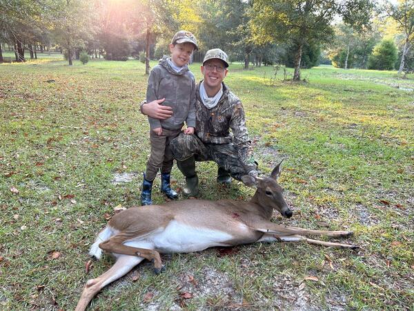
A National Assessment of Pesticide, PFAS, Microplastic, and Antibiotic Resistance Gene Exposures in White-Tailed Deer
Research has documented exposures and consequential environmental health effects of pesticides, PFAS, microplastics, and antibiotic resistance genes in environmental biota. Little is known, however, regarding such effects in white-tailed deer ( Odocoileus virginianus ).

Groundwater Monitoring in McHenry County, Illinois
Groundwater Monitoring in McHenry County, Illinois

Airborne Electromagnetic (AEM) Survey 2023 - Illinois River Basin
The U.S. Geological Survey (USGS) is conducting an Airborne ElectroMagnetic (AEM) Survey starting in late January 2023 and lasting three to four weeks. A helicopter towing a large hoop from a cable will begin making low-level flights over the Illinois River Basin, covering much of central Illinois and parts of northwest Indiana.


")