Full Equations (FEQ) Model for the Solution of the Full, Dynamic Equations of Motion for One-Dimensional Unsteady Flow in Open Channels and Through Control Structures

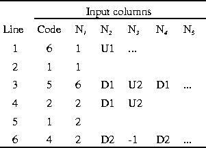
In line 3 for code 5, the first node, D1, defines the upstream node for head; the second node, U2, defines the downstream node for head; and the third node, D1, defines the discharge node. The discharge node must be either of the two nodes for head. In this case, either choice will be valid. In other cases, only one choice will be valid.
The upstream and downstream external boundary conditions are the same as in the single-branch example, and they provide the first and the last equations as above. The internal boundary conditions at the dam are the conservation of mass at a junction, code 2 (eq. 89), and a two-node control-structure, code 5, for the flow over the dam (eq. 102). The internal boundary condition includes only two flow-path end nodes in this case. Therefore, only 2 out of the 10 elements in the row of the Jacobian for the internal boundary condition will be nonzero. The two-node control structure, in the most general state, includes the flow at one flow-path end node and water-surface heights at both flow-path end nodes. Therefore, at most, this row of the Jacobian matrix will include three nonzero elements. As mentioned earlier, the conservation equations for the elements on each branch are preceded and followed by one equation from the boundary conditions that are attached to the branches. This pattern maintains the same bandwidth for the equations on a branch. At upstream and downstream boundaries the assignment is fixed, and the boundary condition is applied to provide the equation at that end of the branch. At junctions, however, the order of assignment is not fixed and is determined by rules internal to FEQ.
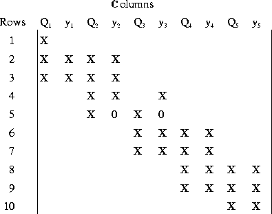
The Jacobian matrix for this example has the following pattern:

An X denotes an element that is nonzero, whereas those elements that are known to be zero are left blank in the matrix. The zeros shown in the matrix are initially zero but may become nonzero. The columns are labeled with the variable involved in that column. In this simple example, the bandwidth is unchanged from that in the single-branch example. Therefore, internal boundary conditions between two branches do not change the bandwidth.