[Next Section]
[Previous Section]
[Table of Contents]
Full Equations Utilities (FEQUTL) Model for the Approximation of
Hydraulic Characteristics of Open Channels and Control Structures During
Unsteady Flow
U.S. GEOLOGICAL SURVEY WATER-RESOURCES INVESTIGATIONS REPORT 97-4037
5.5 CULVERT Command
Update available for flapgate
losses
Purpose: Flows through culverts and over an associated roadway are
computed in this command by use of
methods outlined in section 4.2.
A 2-D table of type 13 is computed in this command. Only standard culverts
and small deviations from standard culverts can be represented with the
CULVERT command. Culverts with drop inlets or other special structural
features that are uncommon in practice cannot be analyzed with the CULVERT
command.
LINE 1
Variable: TABLE
Format: 7X, I5
Example: TABLE #= 9900
Explanation:
|
TABLE gives table number of the 2-D function table computed for the
flows through the culvert. |
LINE 2
Variable: CHAR4, TABTYP
Format: A4, 1X, I5
Example: TYPE = 13
Explanation:
|
CHAR4 must be TYPE.
TABTYP specifies the table type. Types 6 and 13 are currently supported
in the FEQ model. Both table types contain the same information, but type
13 is more compact, takes less table-storage space, and is easier to read.
Type 13 should be used unless type 6 is more appropriate for a specific
application. |
LINE 3
Variable: CHAR6, LABEL
Format: A5, 1X, A50
Example: LABEL = Twin-barrel 54-inch culvert at El Monte Road
Explanation:
|
CHAR6 must be LABEL.
LABEL gives a user-defined label that will appear in the table for identification
purposes. |
LINE 4
Variable: HEAD
Format: A80
Example: Approach-section data
Explanation:
|
HEAD gives a subheading to break the input into logical components.
The subheading may be any text, but should describe the data that follow. |
LINE 5
Variable: CHAR6, APPTAB
Format: A6, 2X, I5
Example: APPTAB #= 342
Explanation:
|
CHAR6 must be APPTAB.
APPTAB gives the table number for the cross-section table of the approach
section for the culvert. This table must have been input with the FTABIN
command (section 5.13) or have been
computed with the SAVE option in the FEQX, FEQXEXT, or FEQXLST commands
(sections 5.8-5.10).
Furthermore, the approach cross-section table must be of type 22 or 25
because values of critical flow are required in the CULVERT command. |
LINE 6
Variable: CHAR6, APPELV
Format: A6, 1X, F10.0
Example: APPELV = 723.10
Explanation:
|
CHAR6 must be APPELV.
APPELV supplies the elevation of the minimum point of the cross section
specified in APPTAB. This elevation should match the bottom-profile elevation
at the downstream end of the branch upstream from the culvert in the FEQ
input. |
LINE 7
Variable: CHAR6, APPLEN
Format: A6, 1X, F10.0
Example: APPLEN = 24.0
Explanation:
|
CHAR6 must be APPLEN.
APPLEN gives the distance between the approach cross section and the
entrance to the culvert. This distance should be about the same as the
opening width of the culvert or the sum of the opening widths of multiple
culverts. This value must be > 0. |
LINE 8
Variable: CHAR6, APPLOS
Format: A6, 1X, F10.0
Example: APPLOS = 0.1
Explanation:
|
CHAR6 must be APPLOS.
APPLOS gives the hydraulic-energy loss resulting from special approach
conditions in terms of the fraction of the velocity head in the approach
cross section. Normally this loss is 0, but it can be used to approximate
the losses resulting from trash racks, right-angle bends upstream from
the culvert entrance, and other entrance conditions. This value should
be between 0 and 1. |
LINE 9
Variable: CHAR6, APPEXP
Format: A6, 1X, F10.0
Example: APPEXP = 0.5
Explanation:
|
CHAR 6 must be APPEXP.
APPEXP gives a coefficient to be applied to the difference between the
approach-velocity head and the velocity head in the culvert entrance if
the culvert is an expansion in flow area instead of a contraction in flow
area. The discharge coefficient for the entrance loss for the culvert is
set to the maximum value for no contraction of 0.98
(Bodhaine, 1968) if the flow is expanding instead of contracting. This
value should be between 0 and 1. |
LINE 10
Variable: HEAD
Format: A80
Example: Culvert Description
Explanation:
|
HEAD provides a subheading for the culvert cross section, elevation,
and length description. |
LINE 11
Variables: CHAR6, NODEID
Format: A6, 1X, A4
Example: NODEID=YES
Explanation:
|
CHAR 6 must be NODEID.
NODEID indicates whether an identifying string for each node along the
culvert is included in the input. If NODEID is YES, then identifying strings
are present; otherwise, they are omitted. At a minimum, each culvert will
have two nodes: the entrance and the exit of the culvert. More nodes may
be needed, however, if the shape or slope of the culvert is changed. Also,
additional nodes may be needed to compute the flow through the culvert. |
LINE 12
Variable: CHAR4, SFAC
Format: A4, 1X, F10.0
Example: SFAC = 1.0
Explanation:
|
CHAR4 must be SFAC.
SFAC gives the multiplying factor that converts the stations in the
input to distances required in FEQUTL. The required distances are in feet
for the ENGLISH unit option and in meters for the METRIC units option. |
LINE 13
Variable: HEAD
Format: A80
Example: NODE XNUM STATION ELEVATION
Explanation:
|
HEAD gives user-defined heading that describes the information on subsequent
lines. |
LINE 14 (Repeated as needed for each node on the culvert.)
If NODEID = NO then
|
Variables: NODE, XTAB, X, Z, KA, KD
Format: 2I5, 2F10.0, 2F5.0 |
If NODEID = YES then
|
Variables: NODE, NAME, XTAB, X, Z, KA, KD
Format: I5, 1X, A8, 1X, I5, 2F10.0, 2F5.0 |
Explanation: The values describing each node on a culvert barrel are given
on this line.
|
NODE is the node number on the current culvert. The end of a culvert-barrel
description is indicated by a negative value of the NODE entry. The remainder
of the line containing the terminating node number may be blank. The number
for the first node on each branch must be given. The NODE
column may be left blank for the other nodes and the node number will
be computed in FEQUTL. If node numbers are given, they must be consecutive
and increasing. The entrance to the culvert is the first node in the table.
NAME is the identification string for the node.
XTAB is the number of the cross-section table computed with the SEWER
(section 5.19), MULPIPES (section
5.17), or MULCON (section 5.16)
command.
X is the station of the node.
Z is the elevation of the minimum point in the stream at the node.
KA is the loss coefficient to apply to the difference in velocity head
when the velocity is increasing in the direction of flow--that is, when
the flow is accelerating.
KD is the loss coefficient to apply to the difference in velocity head
when the velocity is decreasing in the direction of flow--that is, when
the flow is decelerating. |
A culvert may be too long to compute a steady-flow profile by use of
cross sections at its entrance and exit only. Thus, additional nodes and
cross sections must be added. This will be done in FEQUTL computations,
overriding user data if there are at most two cross-section tables specified
to describe the culvert barrel and if only two elevations are specified
to define the slope of the invert. This means that only two nodes are needed
for culvert computations. Only the initial node and the final node on the
culvert barrel are needed in FEQUTL computations. Values of KA and KD specified
on the line for the final node are used for all other nodes added to the
barrel. Internal criteria are used in FEQUTL to define the node spacing
so that the steady-flow profile computations will not result in convergence
problems.
If the culvert-barrel size and shape change in a manner that cannot
be described with just two cross sections, then the user
must assign the
intermediate nodes. Two methods are available for adding intermediate cross
sections. The first method is simple propagation of the last known cross
section at equal station intervals and with linear interpolation for the
profile elevation. This method is selected by one or more blank lines in
the input. A line of complete cross-sectional information above the blank
lines and a line of complete cross-sectional information below the blank
lines must be specified. The upstream table number is assigned to each
blank line, and the stations and elevations are distributed uniformly between
the two lines of known values. Linear interpolation of cross-section characteristics
between two known cross sections is utilized in the second method. This
method is selected by assigning a negative table number for the cross-section
table or, more conveniently, by merely assigning a minus sign in the rightmost
column of the field for the table number. An available table number is
then supplied at the proper time in the FEQUTL computations. This prevents
the problem of the user having to remember which table numbers are available
for interpolated cross sections. If the station and elevation values are
given, they will be utilized in the interpolation. If they are omitted,
the station values will be distributed uniformly and the elevation will
be linearly interpolated. The first method should only be applied if the
conduit is prismatic over the interval of additional cross sections. The
second method should be applied when the conduit characteristics vary over
the interval between the known cross sections.
All cross sections given in the culvert-barrel description must be of
table type 22 or 25 and must have a vertical slot so that a hypothetical
free surface can be computed. The intermediate nodes close to the entrance
and the exit should have small spacing less than one inlet maximum vertical
dimension between them. Conditions change rapidly near these points, and
the distance increment for profile computation should be relatively small.
To compute type 5 flow, there must be one node that is three times the
inlet maximum vertical dimension from the inlet and one node that is six
times the inlet maximum vertical dimension from the inlet. These locations
are needed because the flow contracts to a minimum area (vena contracta)
at a length of about three times the maximum vertical culvert dimension
from the entrance, and in FEQUTL it is assumed that most of the expansion
losses result within a distance of three times the maximum vertical culvert
dimension downstream from the vena contracta (section
4.2.3).
LINE 15
Variable: CHAR6, CULCLS
Format: A6, 1X, A8
Example: CULCLS = BOX
Explanation:
|
CHAR6 must be CULCLS.
CULCLS gives the general class of the culvert for selection of the discharge
coefficient. The culvert class does not determine the shape of the culvert.
Thus, if an irregular-shaped culvert is judged to be best described as
a box culvert for determination of the hydraulic characteristics, then
the culvert class should be specified as BOX even though the culvert is
not strictly a box culvert. The available options are: BOX-box culverts,
PIPE-circular, elliptical, and arch pipes; MITER-mitered entrance for pipe
culverts, RCPTG-reinforced-concrete pipe with machine tongue-and-groove construction
and also pipes with commercially flared entrances. |
LINE 16
Variable: HEAD
Format: A80
Example: Departure section description
Explanation:
|
HEAD gives a subheading for the departure section data that follow. |
LINE 17
Variable: CHAR6, DEPTAB, BEGTAB, RMFFAC
Format: A6, 2X, I5, A5, A5
Example: DEPTAB #= 341
Explanation:
|
CHAR6 must be DEPTAB.
DEPTAB gives the table number of the cross-section table of the departure
section for the culvert. This section represents the stream cross section
where the flow concentration caused by the culvert in the downstream flow
has essentially dissipated.
BEGTAB specifies an optional table number for the cross-section table
describing the departure reach at the exit from the culvert.
RMFFAC is an optional entry that specifies a multiplying factor on the
estimated momentum flux over the roadway. If RMFFAC is omitted, the default
value is 1. This value must be > 0 and 1.
1. |
LINE 18
Variable: CHAR6, DEPELV, BEGELV, DSFFAC, WIDFAC
Format: A6, 1X, F10.0, A10, A5, A5
Example: DEPELV = 629.05
Explanation:
|
CHAR6 must be DEPELV.
DEPELV gives the elevation of the bottom of the departure section. This
elevation should match the elevation of the bottom profile of the upstream
end of the branch downstream from the culvert in the FEQ input.
BEGELV is the elevation of the bottom of the beginning cross section
for the departure reach. The beginning elevation, if omitted, is set as
follows. If DEPELV is greater than the culvert-exit invert elevation, then
BEGELV is set to the culvert-exit invert elevation; otherwise, BEGELV is
set to the same elevation as DEPELV.
DSFFAC is reserved for potential future expansion of FEQUTL and is not
used. The default value for DSFFAC is 0.
WIDFAC is a width factor for checking the beginning cross section of
the departure reach. The default value for WIDFAC is 1.02. |
The validity of BEGTAB may be checked with WIDFAC. BEGTAB represents
the cross section of the departure reach at the culvert exit and must always
be at least WIDFAC wider than the culvert exit. This width increase is
checked at each tabulated water-surface height in the cross-section table
for the culvert barrel, and if the test fails at any tabulated water-surface
height, the cross section in BEGTAB is rejected. A height-by-height report
on the widths of the two cross sections is output in FEQUTL computations.
A cross section for BEGTAB must be input that will not obstruct any part
of the exit cross section for the culvert barrel. If the obstruction is
present and not just an artifact of the manner in which BEGTAB was defined,
then the cross section of the culvert barrel at the exit should be modified
to reflect the obstruction.
LINE 19
Variable: CHAR6, LOSOPT
Format: A6, 1X, A8, F10.0
Example: LOSOPT = MOMENTUM
Explanation:
|
CHAR6 must be LOSOPT.
LOSOPT gives the loss option for the expansion of the flow into the
departure reach. The procedure for culvert flow in Bodhaine
(1968)includes losses resulting from contraction at the culvert entrance
and subsequent expansion in the culvert barrel. The loss caused by the
expansion of the flow in the departure reach must be computed separately.
One loss option, denoted by MOMENTUM, is available in the CULVERT command.
A simple momentum balance in the departure reach is applied to estimate
the losses in the expanding flow in this option. Complete details are given
in section 4.2.5 |
LINE 20
Explanation:
|
Line 20 is not currently used in FEQUTL, but it is reserved for future
expansion of the loss options in the departure reach. This line is retained
to maintain the line number sequence. |
LINE 21
Variable: HEAD
Format: A80
Example: Discharge coefficient data
Explanation:
|
HEAD gives the subheading for discharge-coefficient information. |
The selection of the discharge coefficient involves several factors.
Some of these factors are purely geometric and are not changed by the depth
or flow of water in the culvert. Some of the factors are hydraulic and
depend on the depth or flow of water. Consequently, some discharge coefficients
are determined by geometric factors alone, and some are determined by a
combination of geometric and hydraulic factors. In order to allow for the
greatest flexibility in model simulation and to simplify the input for
the CULVERT command, the discharge coefficients dependent on hydraulic
factors are determined internally in FEQUTL computations. Discharge factors
and adjustment factors that depend on geometry only must be supplied in
the input. However, the values defined by geometry only may be determined
by table look up in FEQUTL computations if requested by the user. Determination
of the values by table look up is the preferred method. However, the ability
to provide explicit values is retained to maintain maximum flexibility.
The values that may be determined by table look up are: the multiplying
factor to adjust the base-discharge coefficient for flow types 1, 2, and
3 for the effect of rounding or beveling of the entrance to the culvert,
KRB; the adjustment factor for the effect of wingwalls on the discharge
coefficient for flow types 1, 2, and 3 when the wingwalls are present for
box culverts, KWING; the adjustment factor for the effect for projecting
entrances for flow types 1, 2, and 3, KPROJ; and the discharge coefficient
for type 4 and 6 flow, C46. To request look up, these four variables are
given the value of 0.0 (in Lines 22-25, respectively). If a nonzero value
for these variables is specified, that value will be applied, and no look
up will be done. The special file TYPE5.TAB (which may be retrieved electronically
as described in section 5.1) must be
input using FTABIN (section 5.13) if
look up is requested. This file contains both flow-type 5 related tables
and tables defining KRB, KWING, KPROJ, and C46. If look up is requested
for any one of these values, the optional input for the flow-type 5 parameters,
Line 25-1, must be given. The input for flow-type 5 parameters has been
expanded to include the geometric variables required to define KRB, KWING,
KPROJ, and C46.
LINE 22
Variable: CHAR3, KRB
Format: A3, 1X, F10.0
Example: KRB = 1.05
Explanation:
|
CHAR3 must be KRB.
KRB gives the multiplying factor to adjust the base discharge coefficient
for flow types 1, 2, and 3 for the effect of rounding or beveling of the
entrance to the culvert. The value should be between 1 and 1.5. The base
coefficient is selected on the basis of the culvert class. Bodhaine
(1968) presented a series of figures that may be used to estimate the
multiplying factor for culverts corresponding to the PIPE and BOX input
descriptions. For sharp-edged entrance conditions, figure 20 in Bodhaine
should be used with the PIPE designation and figure 23 should be used with
the BOX designation. For culverts with rounded entrances, the value determined
from figure 20 or 23 should be multiplied by the value determined from
figure 21. For culverts with beveled entrances, the value determined from
figure 20 or 23 should be multiplied by the value determined from figure
22. |
LINE 23
Variable: CHAR5, KWING
Format: A5, 1X, F10.0
Example: KWING = 1.10
Explanation:
|
CHAR5 must be KWING.
KWING gives the adjustment factor for the effect of wingwalls on the
discharge coefficient for flow types 1, 2, and 3 when wingwalls are present
for box culverts. Values are given in figure 24 of Bodhaine
(1968). The value should be between 1 and 1.25. Wingwalls do not change
the discharge coefficient for a pipe culvert set flush with a vertical
headwall. |
LINE 24
Variable: CHAR5, KPROJ
Format: A5, 1X, F10.0
Example: KPROJ = 0.96
Explanation:
|
CHAR5 must be KPROJ.
KPROJ is the adjustment factor for the effect for projecting entrances
for flow types 1, 2, and 3 (Bodhaine,
1968, p. 41-42). KPROJ is a function of the length of projection as
detailed by Bodhaine (1968, p. 42).
The value should be between 0.9 and 1. |
LINE 25
Variable: CHAR3, C46
Format: A3, 1X, F10.0
Example: C46 = 0.85
Explanation:
|
CHAR3 must be C46.
C46 is the discharge coefficient for culvert-flow types 4 and 6. This
coefficient is purely a function of geometry and must therefore contain
all the adjustments for wingwalls, projecting entrance, rounding, beveling,
and other conditions discussed in Bodhaine
(1968, p. 42-43). This value should be between 0.6 and 1. |
LINE 25-1
Variable: HEAD
Format: A80
Example 1: TYPE 5 flow parameters
Example 2: Type 5 flow parameters
Explanation:
|
HEAD gives heading information for the input of optional type 5 flow
parameters and parameters to define the look up of discharge coefficients
for other flow types. The first six characters of the heading line must
be TYPE 5 or Type 5. The remainder of the line can be any suitable title.
Input of parameters for type 5 flow is optional. However, the file TYPE5.TAB
(retrieved electronically as described in (section
5.1) must be included in an FTABIN (section
5.13) command to provide a variety of tables that define the boundary
between type 5 and type 6 flow and the discharge coefficients for type
5 flow. If the type 5 parameters are omitted, the default values are: RBVALUE
= 0.0, WWANGLE = 0.0, and TYPE5SBF = 0.75 (see Lines
25-2, 25-3, and 25-4). |
LINE 25-2
Variable: RBVALUE
Format: 8X,F10.0
Example: RBVALUE = 0.03
Explanation:
|
RBVALUE is the relative rounding/beveling for the culvert entrance.
This value is used to define the discharge coefficient for type 5 flow.
It also is used to define KRB if table look up is requested by the user.
RBVALUE should be 0 and
0.14. The default value of RBVALUE is 0.0. 0 and
0.14. The default value of RBVALUE is 0.0. |
LINE 25-2-1
Variable: BVANGLE
Format: 8X,F10.0
Example: BVANGLE = 45.0
Explanation:
|
BVANGLE is the angle in degrees of the bevel if the entrance to the
culvert is beveled. If the entrance is rounded or sharp-edged, this value
is 0.0. A nonzero value for BVANGLE indicates that the RBVALUE is utilized
for beveling and not rounding. BVANGLE must be
0 and 90 degrees. RBVALUE and BVANGLE are used
to define KRB if table look up is requested by the user. |
LINE 25-3
Variable: WWANGLE
Format: 8X,F10.0
Example: WWANGLE = 45.0
Explanation:
|
WWANGLE is the wingwall angle in degrees. A value of 0 means that the
plane of the wingwall is perpendicular to the culvert barrel. A value of
90 means that the plane of the wingwall is parallel with the barrel. The
default value of WWANGLE is 0.0. |
LINE 25-3-1
Variable: LPOVERD
Format: 8X,F10.0
Example: LPOVERD = 0.1
Explanation:
|
LPOVERD is the average projection length of the culvert barrel relative
to the culvert maximum inside vertical dimension. LPOVERD must be
0. This value defines KPROJ when table look up is requested by the user. |
LINE 25-4
Variable: TYPE5SBF
Format: 9X,F10.0
Example: TYPE5SBF = 0.75
Explanation:
|
TYPE5SBF is the value of relative water-surface height in the barrel
or the barrel exit that will result in full flow in the culvert barrel.
The relative water-surface height is expressed in relation to the maximum
vertical dimension of the culvert barrel. Thus, a value of 0.75 specifies
that water in the culvert barrel must be flowing at a water-surface height
equal to or greater than 0.75 (the default value determined from engineering
judgment) of the maximum vertical dimension at the exit before full flow
in the culvert will result. TYPE5SBF must be
0 and1. For type 5 flow, submergence and full
flow are considered to have identical flow and hydraulic characteristics.
No effort is made to distinguish between full flow and submergence because
no data on which to base such a distinction are available. |
LINE 25-5
Variable: HEAD
Format: A80
Example: TABLE numbers for type 5 flow
Explanation:
|
HEAD gives a heading for optional input specifying the table numbers
for type 5 flow. These tables provide information of the boundary between
type 5 and type 6 flows, and discharge coefficients for type 5 flow. The
first five characters of the heading must be TABLE or Table. The remainder
of the line can be any suitable heading. The type 5 parameters and table
numbers are specified, and then the type 5 parameter input must be specified
before the table numbers. |
LINE 25-6
Variables: TB6ADR, TB7ADR, TB8ADR, TB15ADR, TB16ADR(1: 4)
Format: free, one or more spaces must separate numbers
Example: 9980 9981 9982 9983 9984 9985 9986 9987
Explanation:
|
Table numbers for tables of information used in computing type 5 flows
are specified in this line. All the tables refer to Bodhaine
(1968). If this information is omitted, the default table numbers are
given in the current example. The default function tables are stored in
a file, TYPE5.TAB, which is available by electronic retrieval as described
in section 5.1. These numbers should
be supplied only if there is some conflict between the default table numbers
and a planned or previously used table-numbering scheme.
TB6ADR is the 2-D table of type 10 representing table 6 in Bodhaine
(1968)-"Discharge coefficients for box or pipe culverts set flush in
a vertical headwall with variation of head and entrance rounding or beveling,
type 5 flow."
TB7ADR gives the 2-D table of type 10 representing table 7 in Bodhaine
(1968)-"Discharge coefficients for box culverts with wingwalls with variation
of head and wingwall angle, , type 5 flow." , type 5 flow."
TB8ADR gives a 1-D table of type 2 representing the discharge coefficients
for flared pipe-end
sections.
TB15ADR gives a 2-D table of type 10 representing the data presented
in figure 13.
TB16ADR(1) through TB16ADR(4) give the table numbers for 2-D tables
of type 10 for the four parts of figure 14. |
LINE 25-7
Variable: HEAD
Format: A80
Example: TYPE 1 parameters
Explanation:
|
HEAD gives a heading for the optional parameters for type 1 flow. These
optional parameters relate to the limits for type 1 flow. The first six
characters of the line must be either TYPE 1 or Type 1. Type 1 parameters
must be specified after the Type 5 parameters if both are specified. The
following defaults are used if this input is omitted: TY1YTD = 0.95
and TY1HTD = 1.4. |
LINE 25-8
Variable: TY1YTD
Format: 7X,F10.0
Example: TY1YTD = 0.95
Explanation:
|
TY1YTD is the relative water-surface height in the culvert-barrel entrance
for the upper limit of type 1 flow. TY1YTD specifies the upper limit for
the type 1 flow rate because the flow rate is determined from critical
depth at the entrance of the culvert barrel. The relative water-surface
height is relative to the maximum vertical dimension of the culvert barrel.
For example, a value of 0.95 indicates the water-surface height in the
barrel entrance will be at 0.95 of the maximum vertical dimension at the
maximum type 1 flow. This limit is needed because critical flow increases
without bound as the water-surface height of the flow approaches the soffit
of a closed conduit with converging walls. TY1YTD must be
0.5 and < 1. |
LINE 25-9
Variable: TY1HTD
Format: 7X,F10.0
Example: TY1HTD = 1.4
Explanation:
|
TY1HTD is the maximum relative head permitted for type 1 or type 2
flow at their upper limits. Experiments and field observations indicate
that full flow in culverts will result if the approach head measured relative
to the invert of the culvert inlet is 1.5 or greater. Full flow may result
at a lower approach head, and for type 2 flow, full flow may begin for
a relative head as small as 1.2. The specification of the relative water-surface
height using TY1YTD may, for culverts other than box culverts, result in
a relative-head ratio that is greater than 1.5. If the ratio is greater
than 1.5, this result is ignored and the relative-head ratio is set to
the value given by TY1HTD in CULVERT- command computations. The type 1
flow conditions at that limit are then computed for the maximum type 1
flow. The limit is not set at 1.5 to permit computation of a transition
zone between the low-head free flows, types 1 and 2, and the high-head free
flows, types 5 and 6. TY1HTD must be 1. |
LINE 26
Variable: HEAD
Format: A80
Example: Roadway description
Explanation:
|
HEAD gives a subheading for the roadway description. A format similar
to that used in the EMBANKQ command is applied here. |
LINE 27
Variable: TAB(1)
Format: 7X, I5
Example: PLCWTB = 9994
Explanation:
|
TAB(1) is the table number for the function table listing the low-head
weir coefficient for a paved surface. The table number in this example
is the default value, and this table may be retrieved
electronically as described in section
5.1. |
LINE 28
Variable: TAB(2)
Format: 7X, I5
Example: GLCWTB = 9995
Explanation:
|
TAB(2) is the table number for the function table listing the low-head
weir coefficient for a graveled surface. The table number listed in this
example is the default value, and this table may be retrieved electronically
as described in section 5.1. |
LINE 29
Variable: TAB(3)
Format: 7X, I5
Example: PHCWTB = 9996
Explanation:
|
TAB(3) is the table number for the function table listing the high-head
weir coefficient for a paved surface. The table number listed in this example
is the default value, and this table may be retrieved electronically as
described in section 5.1. |
LINE 30
Variable: TAB(4)
Format: 7X, I5
Example: GHCWTB = 9997
Explanation:
|
TAB(4) is the table number for the function table listing the high-head
weir coefficient for a graveled surface. The table number listed in this
example is the default value, and this table may be retrieved electronically
as described in section 5.1. |
LINE 31
Variable: TAB(5)
Format: 7X, I5
Example: PSUBTB = 9998
Explanation:
|
TAB(5) is the table number for the function table listing the submergence
correction factor for a paved surface. The table number listed in this
example is the default value, and this table may be retrieved electronically
as described in section 5.1. |
LINE 32
Variable: TAB(6)
Format: 7X, I5
Example: GSUBTB = 9999
Explanation:
|
TAB(6) is the table number for the function table listing the submergence
correction factor for a graveled surface. The table number listed in this
example is the default value, and this table may be retrieved electronically
as described in section 5.1. |
LINE 33
Variable: HEAD
Format: A80
Example: OFFSET CREST WIDTH APPROACH SURFACE
Explanation:
|
HEAD gives a heading for subsequent columns of input. |
LINE 34 (Repeated as necessary to include all offsets describing the
roadway embankment.)
Variables: OFF(I), CREST(I), WIDTH(I), APPROC(I), SURF(I)
Format: 4F10.0, 1X, A8
Explanation: The values given on this line define, subsection-by-subsection,
the geometry of the crest of the roadway applied in computation of flow
over the roadway.
|
OFF is the horizontal offset for which geometric characteristics are
entered on this line.
CREST is the crest elevation.
WIDTH is the width of the crest in the
direction of flow.
APPROC is the elevation of the approach channel. If the approach velocity
should be ignored, then an approach elevation that is much lower than the
crest elevation should be specified so that the computed velocity head
will be small.
SURF is the the type of surface, and the designation applies to the
line segment beginning at the offset for which the surface type is given.
For example, if the first line of the roadway-crest specification gives
the type of surface as GRAVEL and the second line of the roadway-crest
specification gives the type of surface as PAVED, then the roadway crest
between the first and second offset is taken to be of a roughness similar
to a graveled roadway. Two closely spaced points should be placed on the
crest at the change in roughness to represent the transition between the
two surface conditions. The end of the weir specification is indicated
by entering END for the type of surface. Thus, if the third line of the
input in this example contained END for the type of surface, then the weir
crest between the second and third offset would have a roughness similar
to a paved roadway. |
These geometric characteristics are input for the boundaries of the
subsections. The crest elevation, crest width, and approach-channel elevation
are assumed to change linearly between the given points on the crest as
illustrated in figure 18 (in
section 5.6). To make input easier, the values for width, approach-channel
elevation, and surface type propagate downward into fields left blank.
Thus, if the elevation of the approach channel is constant and the width
is constant, only the first line of the specification must contain the
elevation of the approach channel and the width of the weir crest.
LINE 35
Variable: HEAD
Format: A80
Example: Head sequence definition
Explanation:
|
HEAD gives the heading for the parameters listing the sequence of upstream
heads and the distribution of the partial free drops used to define the
downstream heads for the 2-D table. |
LINE 36
Variable: CHAR5, NFRAC
Format: A5, 1X, I5
Example: NFRAC = 11
Explanation:
|
CHAR5 must be NFRAC.
NFRAC is the number of partial free drops used in computing the table.
Complete details on partial free drops are given in the discussion of 2-D
function tables in section 11.2 of
the documentation report for FEQ (Franz
and Melching, 1997). |
LINE 37
Variable: CHAR6, POWER
Format: A6, 1X, F10.0
Example: POWER = 2.
Explanation:
|
CHAR6 must be POWER =.
POWER is the power applied to distribute the proportion of free drop
from a value of 0 to 1. The proportion of free drop is given by
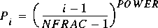
for i = 1, ..., NFRAC.
|
LINE 38 (Repeated as necessary to input all the upstream heads used in
computing the 2-D table.)
Variable: HUVEC(I)
Format: F10.0
Example: 2.0
Explanation:
|
HUVEC is the upstream head to use in computing the 2-D table. The sequence
of heads should be positive and strictly increasing. The end of head input
is signaled by a negative value for head. The heads specified here will
be the values of head that appear in the table. It is the user's responsibility
to choose a spacing that is appropriate for head distribution for the culvert
and roadway embankment simulated. Generally, the spacing should be small
for the low heads and larger for the high heads. The head interval should
become small when flow over the roadway, if any, begins. A spacing of 0.1
ft or even 0.01 ft may be needed to define the low-head range of the table
if the range of heads is small. Generally, no more than about 20 subdivisions
should be used to represent the range of heads expected. More subdivisions
can be used, but this results in larger tables. |
[Next Section]
[Previous Section]
[Table of Contents]