SMOOTH is the value of the velocity difference,  V
, for smoothing the losses near the point of zero
difference in velocity head. If SMOOTH = 0.0, then no
smoothing is done.
Full Equations Utilities (FEQUTL) Model for the Approximation
of Hydraulic Characteristics of Open Channels and Control
Structures During Unsteady Flow
Purpose: A 2-D table to approximate the flow through a channel transition is computed in the EXPCON command. The transition is defined by an upstream cross section, a downstream cross section, the bottom elevations, the distance between the sections, and parameters relating to the computation of friction and shock losses. The methods utilized in FEQUTL are discussed in section 3.2.
LINE 1
Variable: HEAD
Format: A80
Example: CROSS SECTION TABLES
Explanation:
|
HEAD gives a heading for the information to follow. Heading can be any string, but it must appear as the first item of input after the EXPCON command. |
|
HEAD gives the headings for the columns of information to follow. |
|
CHAR4 must be UP or an error statement is issued. XTABL is the function-table number of the upstream cross section. XL the distance value associated with that cross section. ZBL is the bottom elevation of the cross section. |
LINE 4
Variables: CHAR4, XTABR, XR, ZBR
Format: A4,I5,F5.0,F10.0
Example: DN 940 121. 652.7
Explanation:
|
CHAR4 must be DN or an error statement is issued. XTABR is the function-table number of the downstream cross section. XR is the distance value associated with that cross section.ZBR is the bottom elevation of the cross section. |
LINE 5
Variable: HEAD
Format: A80
Example: COEFFICIENTS AND OUTPUT TABLES
Explanation:
|
HEAD describes the information that follows in the input. |
LINE 6
Variable: HEAD
Format: A80
Example: DIR TAB # KA KD LABEL
Explanation:
|
HEAD provides headings for the columns of information to follow. |
|
Information for the table describing flow from upstream to downstream is specified on this line. CHAR4 must be UD. UDTAB is the table number for the table to be computed.KACCUD is the loss coefficient to apply to the velocity-head difference for accelerating flow. KDECUD is the loss coefficient to apply to the velocity-head difference for decelerating flow. LABUD is a label to print with the output table for identification. |
LINE 8
Variables: CHAR4, DUTAB, KACCDU, KDECDU, LABDU
Format: A4,I5,F5.0,F5.0,1X,A50
Example: DU 301 0.2 0.4 TEST OF THE EXPCON FEQUTL CODE: DU
Explanation: Information for the table describing flow from
downstream to upstream is specified on this line.
|
CHAR4 must be DU.
DUTAB is the table number for the table to be computed. If DUTAB = 0, then no table for flow from downstream to upstream is produced. The remaining information for Line 8 must be supplied and valid. KACCDU is the loss coefficient to apply to the velocity-head difference for accelerating flow. KDECDU is the loss coefficient to apply to the velocity-head difference for decelerating flow. LABDU is a label to print with the output table for identification. |
LINE 9
Variable: SMOOTH
Format: 7X,F10.0
Example: SMOOTH = 0.2
Explanation:
|
SMOOTH is the value of the velocity difference, |
|
TGMEAN is the value of the parameter, |
|
HEAD is a descriptive label for subsequent input. |
LINE 12
Variable: NFRAC
Format: 6X,I5
Example: NFRAC = 11
Explanation:
|
NFRAC is the number of partial free flows to use in computing the 2-D table of type 14. Complete details on partial free flow are given in the discussion of 2-D function tables in section 11.2 of the documentation report for FEQ (Franz and Melching, 1997). |
|
POWER is the power used to distribute the partial free-flow factors between 0 and 1. The partial free flow is given by
|
LINE 14 (Repeated as necessary to input all the downstream
heads used in computing the 2-D table.)
Variable: HDVEC(I)
Format: F10.0
Explanation:
|
HDVEC is the downstream piezometric head applied in computing the table. The downstream piezometric heads are entered in an ascending sequence. The input of the list is terminated when a negative head is encountered. The datum for heads is the maximum of the two elevations for the cross sections defining the transition. |
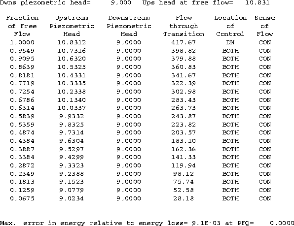
Note: Results for each downstream head are printed with EXPCON. The upstream piezometric head at free flow and information on the partial free flows are listed. An example of this output is given below. The location of the control can be UP, DN, or BOTH. The string BOTH denotes that the control is submerged and that both the upstream and downstream conditions define the flow. The sense of the flow is EXP for expanding flow and CON for contracting flow. The upstream piezometric head need not be greater than the downstream piezometric head. In this example, the upstream piezometric head is greater than the downstream piezometric head because the flow is contracting throughout the transition. A check on the convergence tolerances is given at the end of the table. The check gives the maximum error in the energy balance (in terms of head) relative to the change in energy and location. In this message, PFQ is an abbreviation for Partial Free Flow.
